Automated Alignment (unsupported)
Using cameras and computer vision algorithms, this feature adds a one-step “Auto Align” button to each of the three alignment stages (Red Ball, Grid, and Vertex Tweak). Our experience has been that under good lighting conditions, the automated alignment does an acceptable job by itself. Each step of automated alignment can be further improved through manual adjustments by an experienced person. At this point, automated alignment is intended to provide a good first step in aligning.
The use of automated alignment requires the purchase and installation of additional hardware beyond the basic SOS installation. Costs for the additional hardware should be around or under $2,000. For more information about what hardware is required, please contact sos.support@noaa.gov.
Limitations
Permalink to LimitationsWe consider this to be an experimental capability due to limited testing outside of our development environment. We have excellent control of ambient lighting at our SOS facility. Some of the computer vision algorithms can be thrown off by ambient light or by direct light shining on the sphere. Ongoing development should improve the algorithms over time.
Hardware
Permalink to HardwareWe use four Point Grey GigE machine-vision cameras for auto alignment. (One for each SOS projector) Each camera should be mounted as close as reasonable to the lens of the corresponding projector. At our site, each camera is mounted directly on top of the projector.
Cat5 Ethernet cabling connects each webcam to the SOS computer. We’ve tested the cameras on cables as long as 300 feet with good results. At our site, each computer has one extra Ethernet Card devoted to communicating with the auto alignment cameras. We run one Ethernet cable to a 5 port PoE (Power over Ethernet) networking switch near the projectors. From that switch, we run individual cables to the cameras. The Ethernet cable provides both communication and power to the cameras.
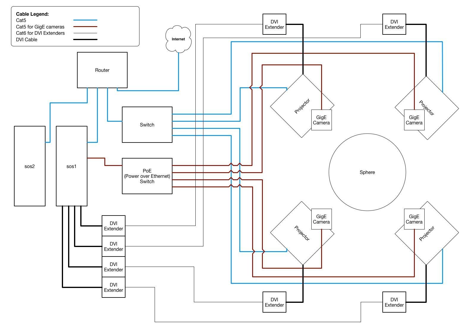
Wiring diagram for an SOS system with cameras for auto-alignment.
Installation
Permalink to InstallationOnce the cameras are physically in place you will need to do a few more steps to fully configure them to work with SOS.
First, you’ll need to set up a new Ethernet connection for the computer to use. To do so, open the Network Manager and add a new configuration as a “Link Local Address”.
Network Configuration
Permalink to Network Configuration-
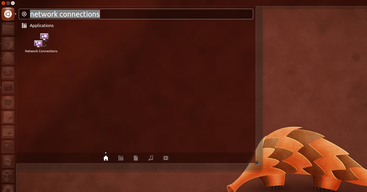
Open the “Network Connections” program. You can open the Ubuntu menu and type “network connections” into the search bar to find it
-
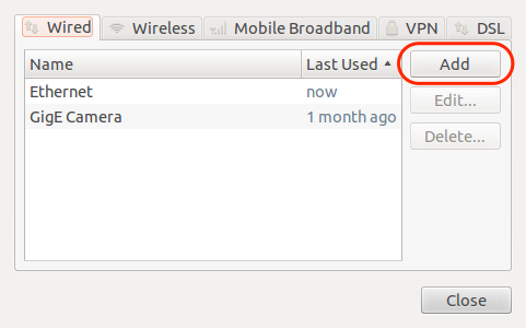
Select “Add” to add a new connection
-
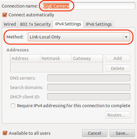
Name the new connection and change the “Method” to “Link-Local Only”. Click “Save…"
Focus Adjustment
Permalink to Focus AdjustmentSecond, you will need to adjust the focus on the lens. You may find this easier to do with two people. To start, open the SOS Utilities program and select the “Start Auto Alignment camera stream” option.
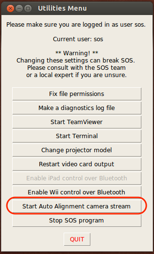
The auto-alignment camera stream can be started from the SOS Utilities menu.
You should then adjust the focus on the lens using the adjustment screw closest to the camera body until the image is in focus. You may also need to adjust where the camera is pointed so that the sphere is in the frame.
Color Configuration
Permalink to Color ConfigurationIf you have good control over the ambient lighting in your exhibit auto alignment will most likely work out of the box. However, if you have ambient light in your exhibit you may need to edit the color definitions.
New in this version is the ability to specify a color range for each projector. It does require some use of the terminal and you will want to ensure that light conditions will remain similar to the conditions you had when you setup your config file. (The less ambient light, the better) If auto alignment isn’t returning satisfactory results and you would like to try modifying the color definitions, you should try the following.
In a terminal, enter
cp /shared/sos/etc/auto_align/default_colors.yaml ~/auto_align_colors.yaml
Then, open the auto_align_colors.yaml file in your home directory with a text editor.
%YAML:1.0
HLS_color_definitions:
    p1:
        red:
            Hue:
                min: 170
                max: 32
            Lightness:
                min: 40
                max: 255
            Saturation:
                min: 64
                max: 255
        cyan: (etc…)
A snippet of the auto_align_colors.yaml config file.
In the file projectors are defined by “p1, p2, etc…”, the color you’re editing is defined by the “red” or “cyan” markers. And the color values are defined by the “Hue, Lightness and Saturation” components. Each color component has a minimum and maximum value.
An aside about the color components. Most people are familiar with colors definied by RGB values. Auto Alignment uses colors defined in the HLS color-space (HLS is also known as HSL). A bit about each value:
- Hue
- Valid numbers are from 0 to 180. Hue is measured in degrees and so values can wrap around 180 back to 0. It represents the base color. (red, yellow, etc…)
- Lightness
- valid values are from 0 to 255. Lightness does not wrap. Lightness determines if your color has a dark hue or a light hue. (dark red vs light red) 0 is black, 255 is white
- Saturation
- valid values are from 0 to 255. Saturation does not wrap. Saturation can be thought of as representing the amount of color. 0 can be thought of as “dull” while 255 is “vibrant” color
More about the HLS color-space can be found online. Wikipedia’s entry provides a good overview.
Please don’t change the formatting of the file, just update the values. If the format is changed, you can always re-copy the default_colors.yaml file and re-enter your custom values.
You will want to update the values in this file based on the information you obtain from the “sampleImage” utility included with SOS. The utility is run on the diagnostic images output by the auto alignment algorithms. The images will be stored in /tmp after running auto alignment. You can run the utility by executing /shared/sos/bin/sampleImage in a terminal.
Example
Permalink to ExampleAfter running redball alignment, you want to update the colors, so you run:
/shared/sos/bin/sampleImage /tmp/imageLeft2.jpg
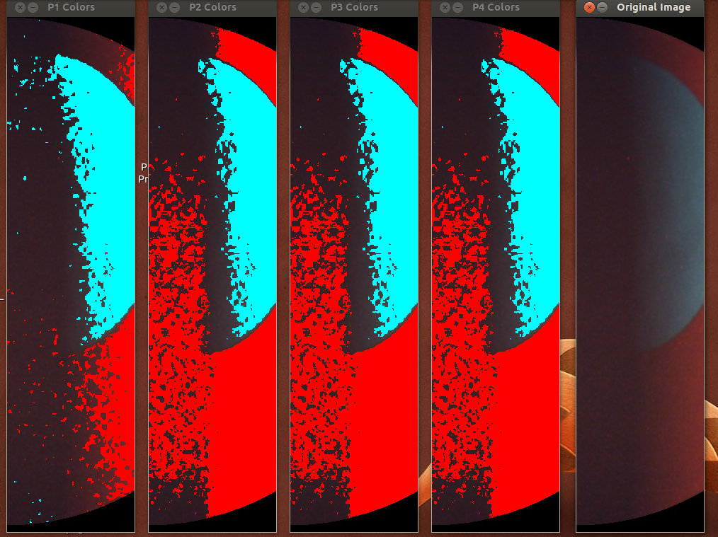
Four images rendered using the color definitions for each projector (P1–P4 Colors) along with the Original Image.
You will see the original image obtained by the camera along with 4 renderings of that image as the algorithms see it once a projector’s color definition is applied. You will really only need to reference one of the images. The numbers in an image’s filename correspond to the projector they were taken from. Since this image belongs to projector 2 we will focus on the rendered image labelled “P2 Colors”.
As you can see in the “P2 Colors” image, the camera is finding extra red in the image and is finding less cyan than it should be. You can click on the “Original Image” and the software will print the HLS values for the pixel clicked in the terminal. You can use these values to determine how to change the color definitions in the auto_align_colors.yaml file.
It may take a few tries before you find set of color definitions that work well for your site. We recommend you try this using the redball step. The imageLeftX.jpg and imageRightX.jpg images are what we usually use to tweak our color definitions.
Software
Permalink to SoftwareAutomatic alignment has been integrated into each of the 3 steps of the Alignment menu of the SOS Remote app. The following section has been added to the bottom of the user interface:
Pressing the Start button will run an automated alignment for the current alignment step. While the automated alignment is running, a progress bar will update as the alignment proceeds. The progress bar is only an approximation, since the time required for each step is not fixed. An automated Red Ball alignment takes approximately 8-10 minutes. Automated alignment for the Grid and Vertex Tweaking steps each typically take 2-4 minutes. While the automated alignment is in progress, the corresponding manual alignment controls are disabled. When the automated alignment completes, the manual alignment controls are available for additional refinement of the results.
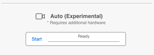
Controls for starting auto-alignment in the SOS Remote App Alignment UI.
As with a manual alignment, the results of the automated alignment are not automatically saved to disk. When the user is satisfied with the alignment, they must press the Save button to permanently save the results to disk. As with a manual alignment, the Revert button will revert the alignment state to the last Saved version.
Diagnostics
Permalink to DiagnosticsSince automated alignment is somewhat experimental, we provide a few diagnostics that might prove useful, perhaps for the curious user or for the benefit of the SOS development team. Each of the three automated alignment steps writes a log file in the soslogs directory below the sos user’s home directory. The files are named redballSideAlignment.log, gridAlignment.log, and vertexTweakAlignment.log. From a terminal window you can use the tail -f command to watch the alignment progress.
tail -f ~/soslogs/redballSideAlignment.logThis command will show lots of magical numbers that the grid alignment is using in its calculations.
There are also some key image files written to the /tmp directory, which can be viewed with the display command. The files /tmp/CameraN_sphere_loc.jpg (where N is 0–3) show a green circle where the software thinks the sphere is in the corresponding camera’s view. The files /tmp/IdentifyCameraN.jpg (where N is 0–3) shows which projector is viewed by each camera. Some additional image files are written to /tmp at key points of the computer vision algorithms.