 Science On a Sphere
Alignment Manual
What is Alignment?
Permalink to What is Alignment?SOS is a room-sized display system that uses four projectors to display planetary datasets on a 6 foot diameter sphere. The projectors are located about 17 feet away from the center of the sphere and are mounted approximately 90 degrees apart from each other. Each projector displays a portion of a dataset (which is either an image or a video) onto its quadrant of the sphere.
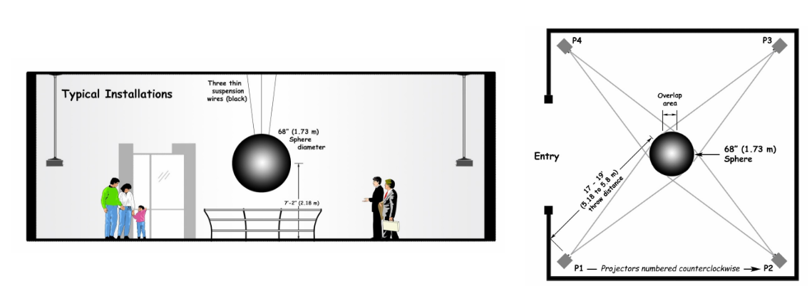
Light from adjacent projectors overlap and create edges in these overlap regions (also called blend regions). This causes the appearance of disjoint images in the areas of overlap. Projector alignment is the process that allows a dataset to be displayed by four projectors such that the dataset appears as one continuous image wrapped around the sphere, rather than four disjoint images.
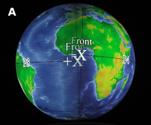
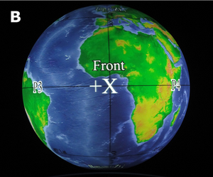
The first image shows the overlap region between two misaligned projectors; the two images look disjointed. The second image shows the same overlap region when both projectors are aligned; the two images look continuous.
Requirements
Permalink to RequirementsIf this is the first time you are doing alignment, you will need anywhere from 1 to 2 hours to complete the alignment process. For first time users, it takes some practice, so be patient. If you have done alignment before, or if the alignment is just being tweaked, the process may take anywhere from 15 minutes to 1 hour to complete, depending on what point in the process you are starting at.
To perform projector alignment for an SOS installation, you need to have access to the main SOS computer. (For sites that are still using the 5-computer system, you will only need access to the main SOS NC computer.) In order for alignment results to be saved, you must be logged in as user “sos”.
You need to have an iPad installed with a copy of the “SOS Remote” (the iPhone or iPod Touch also supports alignment, but these devices are deprecated). This app is available for free download from Apple’s App store. You will need Wi-Fi or Bluetooth access to connect your mobile device to the SOS computer.
Support
Permalink to SupportIf you have any questions regarding alignment, please email sos.support@noaa.gov.
Phase 1: Setup
Permalink to Phase 1: SetupStep 1: Turn on the Projectors
Permalink to Step 1: Turn on the Projectors“ProjectorControl.gui” is an application that allows you to easily switch your projectors ON or OFF at the click of a button. This application is typically set up on your SOS computer by the SOS Team during installation.
If this application is not already running on your SOS computer’s Desktop, double click the “Projector Control” icon located on the Desktop. Then, click the “Turn Projectors ON” button.
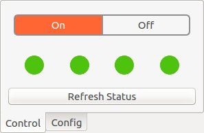
The “Projector Control GUI” shows that all four projectors are turned on and have encountered no errors.
If this application was not installed at your site, turn on each projector by using the projector’s remote control.
Step 2: Set Projector Settings
Permalink to Step 2: Set Projector SettingsHigh Altitude Mode
Permalink to High Altitude ModeAt high altitudes, a projector can overheat due to low air density. If your site is located at a high altitude, set this mode to ON. This will allow the projector to operate with a faster fan speed to prevent damage.
Lamp Mode
Permalink to Lamp ModeIf a room is reasonably dark, use the projector’s lower lamp mode setting (if this feature is available). If the room is bright, set the projector to a higher lamp mode setting for greater light output. In general, all projectors should have the same lamp mode setting so that one projector is not brighter or darker than the others.
Lens Shift
Permalink to Lens ShiftIf your projector has the option for lens shift, in most cases it is best to leave the lens at its default position (i.e., where the center of the projected image aligns directly with the center of the projector’s lens). Ideally, you want the center of the projected image to hit the sphere equator. If the physical placement of the projector does not allow for this, first try tilting the projector (only slightly) so the center of the projected image hits the equator. If this does not work, then try adjusting only the vertical lens shift. If your projector has horizontal and/or diagonal shift, keep these shifts at their default settings.
Keystone Correction
Permalink to Keystone CorrectionIf your projector is mounted such that it is tilting up or down instead of mostly straight, you may have to use the projector’s keystone correction feature to make the projected image more rectangular. For most sites, however, we recommend you do not use any keystone correction.
Resolution
Permalink to ResolutionThe projector’s resolution should be set to its native resolution. Many projectors offer a higher resolution option that is greater than the native resolution. Regardless, you still need to use the projector’s native resolution.
Zoom and Focus
Permalink to Zoom and FocusAfter the lens shift has been adjusted, adjust the projector’s zoom (either manually from the projector’s lens or via the projector’s remote if this option is available). To figure out how far to zoom in or out, first open the Red Ball onto the sphere (see the Red Ball Alignment section). The Red Ball should be fairly centered on the sphere due to physical projector placement. Then, adjust the zoom so that the Red Ball overshoots onto the wall behind the sphere only slightly. Finally, focus the image by looking at the center of the sphere near the equator and using the focus adjustment on the projector or projector’s remote.
Step 3: Edit the SOS Configuration File
Permalink to Step 3: Edit the SOS Configuration File- Measure the height (in inches) from the ground to the sphere’s equator. Write this value down
- For each projector, measure the height (in inches) from the ground to the center of the projector’s lens. Write each value down
- For each projector, measure the distance (in inches) from the center of the projector’s lens to the center of the sphere. Write each value down.
- Write down the native resolution of the projectors, the number of projectors in the display, and the total degrees used by the display (for example, 4 projectors covers 360 degrees longitude, while 3 projectors covers 270 degrees longitude).
- Log on to the main SOS computer as the user “sos”. The sos account is set up with administrative privileges and is necessary for editing alignment files. The sos account password will be what was provided to you during installation
- Open the SOS Configuration Manager by selecting the “Edit SOS Settings” option in the SOS Utilities application on your Desktop. (If you are using SOS version 5.4 or below, you will have to directly edit and save changes to the config file called “sos_stream_control.config”, which is located in the directory /home/sos/. Go ahead and open this file)
- Modify the appropriate values in the config manager to match what you wrote down
- Save the configuration and then close the manager
Step 4: Start the SOS Application on the SOS Computer
Permalink to Step 4: Start the SOS Application on the SOS ComputerIn order to perform projector alignment, the main SOS application, called “SOS Stream GUI”, must be open and running on your SOS computer. If it is not running, double click on the “Start SOS” icon located on the SOS computer’s Desktop to launch the application.
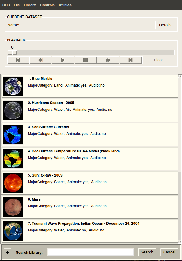
Step 5: Open the Alignment Interface in the SOS Remote App
Permalink to Step 5: Open the Alignment Interface in the SOS Remote AppTo open the Alignment interface on your iOS device, tap on the “SOS Remote” app icon located on the home screen.
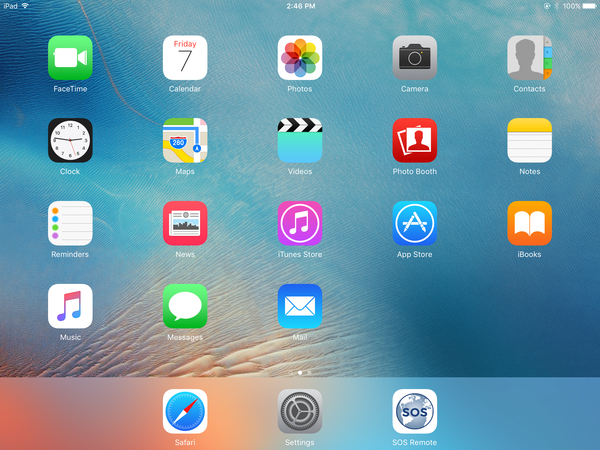
Then, tap on the “Settings” tab.
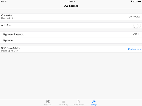
Select the “Alignment” option. A warning message will pop up. Select “Yes” to continue.
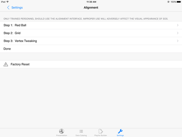
A white grid against a red background will be displayed on the sphere.
Step 6: Factory Reset
Permalink to Step 6: Factory ResetTo reset the projectors to their default alignment settings, tap on the “Factory Reset” button located on the Alignment page. A warning message will pop up. Select “Yes” to proceed with the Factory Reset.
Phase 2: Align the Projectors
Permalink to Phase 2: Align the ProjectorsThe following 3 steps use the SOS software to bring the projectors into alignment. If this is the first time the projectors are being aligned, or new projectors have been swapped in for old ones, or the alignment is significantly off, start with the next step, Step 7: Red Ball Alignment.
However, if the projectors are mostly aligned and just need some tweaking in a few places, you can proceed to Step 8: Grid Alignment or Step 9: Vertex Tweaking.
The closest projector to the SOS computer is typically called projector 1 (P1). The other projectors are named sequentially from 2 to 4 in a counterclockwise direction.
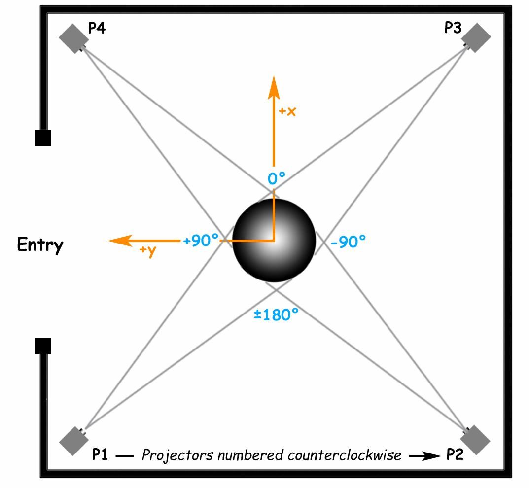
An example arrangement of the four projectors and sphere orientiation in an SOS installation. The entry to the room may be at a different location for your site.
Step 7: Red Ball Alignment
Permalink to Step 7: Red Ball AlignmentIn “Red Ball Alignment”, a red ball against a cyan background is displayed by each projector onto the sphere. The goal of Red Ball alignment is to have the red ball cover the surface of the sphere in front of the projector and not overshoot the sphere on any side. You also do not want to see any cyan on the sphere.
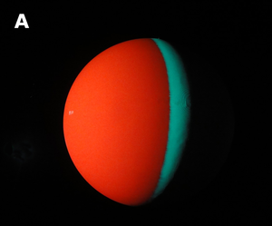
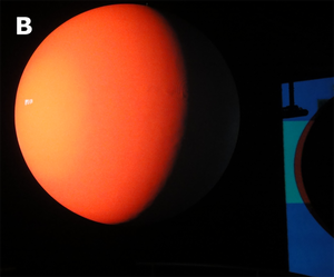
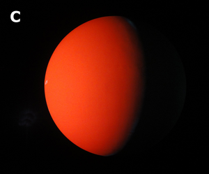
The first image shows the red ball displayed by one projector with the cyan background visible on the sphere. The second shows the red ball displayed by one projector with the red overshooting onto the room's wall. The final image shows the red ball displayed by one projector with no cyan background showing on the sphere and no overshooting of the red ball onto the wall.
- Tap the "Red Ball" option on the Alignment page to bring up the Red Ball interface. Each projector will display a red ball onto the sphere
- During Red Ball alignment, only one projector should be on at a time. Toggle off all projectors except for projector 1. To do this, tap the “P2” button and then tap the “On/Off” button to toggle projector 2 off. Repeat for projectors 3 and 4. Now, tap “P1” so that projector 1 is the currently selected projector
- Use the Translate, Scale, and Rotate controls to adjust the position and size of the red ball of projector 1 so that the red ball covers up the cyan background, and the red ball does not overshoot the sphere on any side. See Positioning the Red Ball for more information
- Tap the “Save” button to save the changes you just made. Note that you can select “Save” at any time during the alignment process, and it is recommended that you save your changes often. Also note that saving will save the changes for all projectors at once, not just the currently selected projector. If changes are made that you don't want to keep, you can revert back to the last time you saved by tapping the “Revert” button
- Repeat steps B, C, and D for projectors 2, 3, and 4
- Tap on the “Done” button to return to the main Alignment page. In this step, it is important to make sure that the red ball is evenly positioned on the sphere for each projector
Positioning the Red Ball
Permalink to Positioning the Red Ball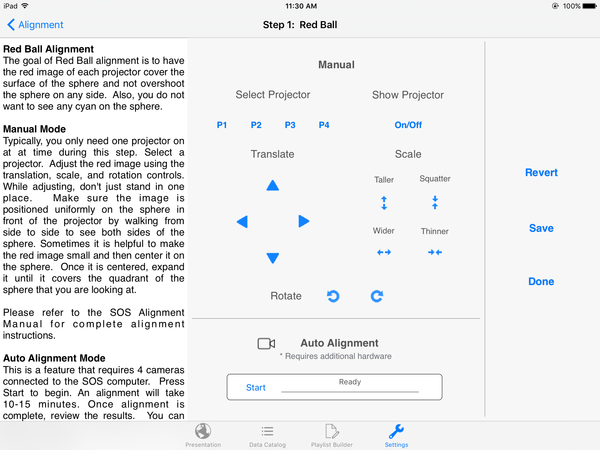
The interface for adjusting projectors during “Red Ball Alignment”.
One way to ensure evenness during step C above is to first stand in front of the projector. Then, use the Scale controls to evenly scale the red ball down to a small enough size so that you can see cyan color all around the red ball (top, bottom, left, and right). Then, use the Translate controls to center the red ball so that the cyan color is even all around the red ball. To check the evenness of the cyan color, you will have to keep walking from side to side of the red ball as you are adjusting and looking up and down.
Once the red ball is centered, use the controls to expand it until it covers the quadrant of the sphere that you are looking at. As much as possible, you want to prevent the red ball from overshooting onto the room’s walls, and you want to cover up most of the cyan. If a tiny bit of cyan color is still showing on one side or another of the sphere, that is okay. Also important is to look at the wall opposite the projector and make sure that the top and bottom of the sphere is not getting cut off due to overshooting.
Step 8: Grid Alignment
Permalink to Step 8: Grid AlignmentIn Grid Alignment, a white grid against a red background is displayed by each projector onto the sphere. The goal of Grid Alignment is to have the grids line up between all the projectors so that there appears to be one seamless image wrapped around the sphere.
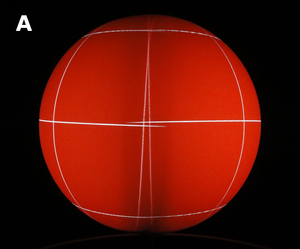
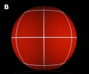
The first image shows the grids from two projectors that are unaligned in the overlap region. The second image shows the grids from the same two projectors after being aligned.
- Tap the "Grid" option on the Alignment page to bring up the Grid interface. Each projector will display a white grid against a red background onto the sphere
- Tap the “P1” button to select projector 1. In Grid Alignment, you typically want all projectors on most of the time. However, it is often handy to intermittently toggle adjacent projectors on or off in order to see which projectors are causing misalignment in the overlap regions. To toggle a projector on or off, tap on a projector button to select that projector, and then tap the “On/Off” button to toggle it on or off
- Use the Translate, Scale, and Rotate controls to adjust the position and size of the grid displayed by projector 1. You want the grid to line up as closely as possible to the grid lines displayed by the projectors to the left and right of projector 1. The controls for Grid alignment affect the projector’s grid as a whole. You cannot alter specific lines on the grid. See Aligning the Grids for more information
- Tap the “Save” button to save the changes you just made. Note that you can select “Save” at any time during the alignment process, and it is recommended that you save your changes often. Also note that saving will save the changes for all projectors at once, not just the currently selected projector. If changes are made that you don't want to keep, you can revert back to the last time you saved by tapping the “Revert button
- Repeat steps B, C, and D for projectors 2, 3, and 4
- Tap on the “Done” button to return to the main Alignment page
Aligning the Grids
Permalink to Aligning the Grids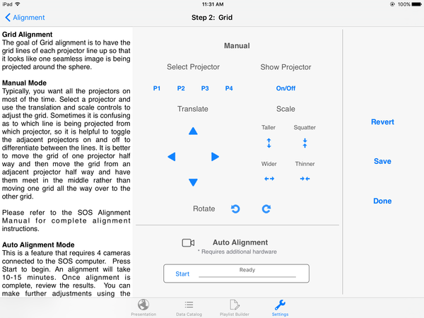
The interface for adjusting projectors during “Grid Alignment”.
During step C above it is better to move the grid of one projector half way and then move the grid from an adjacent projector halfway and have them meet in the middle rather than moving one grid all the way over to the other grid. To do this, you will have to switch over to the adjacent left or right projector in order to adjust their grids slightly, and then switch back to projector 1 to readjust it.
When trying to adjust a grid, it can be confusing as to which projector is displaying which grid. So again, remember to toggle projectors on/off to be clear on which projector is displaying which grid and which projector’s grid lines actually need to be moved.
Remember that even though we may be adjusting multiple projectors (for example, projector 1 plus the adjacent projectors), our intent here is to focus on projector 1 while toggling between the adjacent left and right projectors (projectors 2 and 4 — see diagram at beginning of document for room and projector layout). With this in mind, it is important to just focus on the seams (the overlap regions) between projectors 1 and 2 and projectors 1 and 4.
Tips
Permalink to Tips- In most cases, only the translation and scale controls will be used, and you will not need to use the rotation controls, as rotating will rotate the lines parallel to the equator out of horizontal, which in general we want to avoid
- When performing Grid Alignment for the first time, adjust the horizontal grid lines of all projectors first (via translating in the up/down directions - with the aim to get the horizontal lines evenly sitting along the equator as much as possible), then adjust the vertical grid lines (via translating in the left/right directions), and then scaling to further match the vertical/horizontal lines
- If the top vertical lines between two overlapping projectors (let’s say p1 and p2) are together, but their bottom vertical lines are crisscrossing, though it might not be intuitive, translate both p1 and p2 up by one or more pixels and see if that improves the alignment in the bottom area. Same idea if the top vertical lines are crisscrossing…in this case, translate both p1 and p2 down by one or more pixels
- At the end of Grid Alignment, if you get to the point where you can’t fix one grid without making the adjacent worse, try Vertex Tweaking those areas
Step 9: Vertex Tweaking
Permalink to Step 9: Vertex TweakingOnce the image is fairly close to being seamless, Vertex Tweaking is the final step used to further perfect the alignment. In Vertex Tweaking, a set of numbered vertices corresponding to specific areas of the grid image are displayed by each projector onto the sphere. The goal of Vertex Tweaking is to fine-tune the alignment near these specific areas.
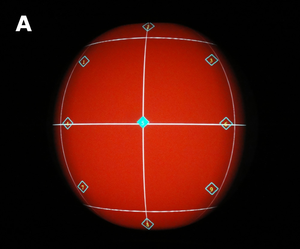
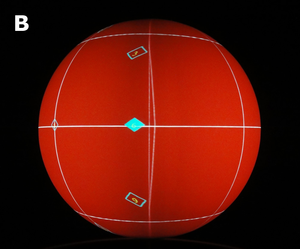
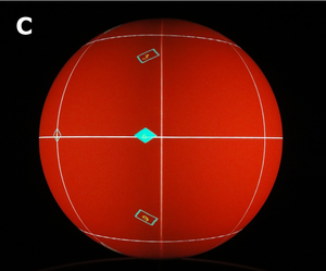
The first image shows the set of vertices displayed by one projector (the two adjacent projectors have been turned off). The second image shows the overlap region between two projectors, with the vertices displayed by the projector on the left. A selected vertex (a numbered diamond shape filled in with cyan color) is also shown. The line near this vertex is out of alignment. The final image shows the overlap region after the Vertex Tweaking procedure; the line near the selected vertex is in alignment.
- Tap the "Vertex Tweaking" option on the Alignment page to bring up the Vertex Tweaking interface. Each projector will display a white grid against a red background onto the sphere
- Tap the “P1” button to select projector 1. A set of numbered vertices will be displayed onto the sphere by projector 1. In Vertex Tweaking, you typically want all projectors on most of the time. However, it is often handy to intermittently toggle adjacent projectors on or off in order to see which projectors are causing misalignment in the overlap region. To toggle a projector on or off, tap a projector button to select that projector, and then tap the “On/Off” button to toggle it on or off
- Select a vertex you would like to adjust by tapping on one of the vertex buttons labeled “1” through “9”. Use the Translate controls to move the image up, down, left or right. The image will only stretch near the selected number. So for example, if a whole side needs to move left, you need to stretch it by adjusting the top, middle, and bottom vertices to the left. See Tweaking Vertices for more information
- Tap the “Save” button to save the changes you just made.Note that you can select “Save” at any time during the alignment process, and it is recommended that you save your changes often. Also note that saving will save the changes for all projectors at once, not just the currently selected projector. If changes are made that you don't want to keep, you can revert back to the last time you saved by tapping the “Revert button
- Repeat C and D for any other vertices you would like to adjust for projector 1
- Repeat B, C, D, and E for projectors 2, 3, and 4
- Tap on the “Done” button to return to the main Alignment page
- This completes the alignment process. Tap the “Settings” back button on the navigation bar of the Alignment page to get back the main Settings page
Tweaking Vertices
Permalink to Tweaking Vertices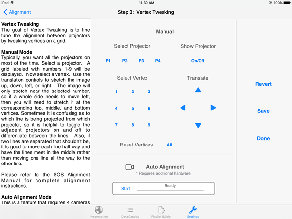
The interface for adjusting vertices during “Vertex Tweaking”.
It is sometimes confusing to figure out which projector is displaying a grid line in the overlap region, so it is helpful to toggle the adjacent projectors on and off to differentiate between the grid lines and to know which projector’s grid line actually needs to be moved.
Also, if two lines from two adjacent projectors are separated that shouldn’t be, it is better to move each line from each projector half way and have them meet in the middle rather than moving one line from one projector all the way to the other. To do this, you will have to switch over to the adjacent left or right projector, adjust that projector’s relevant vertex slightly, and then and then switch back to projector 1 to readjust its relevant vertex.
Remember that even though we may be adjusting multiple projectors (for example, vertices of projector 1 plus the vertices of the adjacent projectors), our intent here is to focus on projector 1 while toggling between the adjacent left and right projectors (projectors 2 and 4 — see diagram at beginning of document for room and projector layout). With this in mind, it is important to just focus on the seams (the overlap region) between projectors 1 and 2 and projectors 1 and 4.
Alignment Tips
Permalink to Alignment Tips- When adjusting grids in Grid Alignment or Vertex Tweaking modes, if you find that you need to make more than one adjustment (for example, one tap of the translation control), then switch back and forth between adjacent projectors so that the grid lines will eventually “meet in the middle”
- It is recommended that the projectors are on for 15-20 minutes before starting alignment as we have found that the images sometimes move slightly as the projectors warm up
- It is recommended that you save the alignment several times throughout the alignment process so that if you adjust a projector but immediately decide that you need to revert that adjustment, you will be taken back to the most recently saved alignment that you were satisfied with
- If your projectors are significantly out of alignment, don’t just use Vertex Tweaking to try to fix it. Vertex Tweaking is meant only for fine local adjustments. If you just use Vertex Tweaking for gross alignment, you may begin to see significant image tearing and other artifacts on the sphere. Go through each of the 3 alignment steps (Red Ball, Grid, Vertex Tweaking) in order to fix the alignment
- If you are checking your alignment every few weeks, and you find that the alignment is only slightly off, often times this indicates that a projector has been slightly moved (maybe due to a projector being bumped, room vibration from large crowds, etc). Try using the Grid alignment interface and only the Translate controls to adjust it. This may be enough to bring the projector back into alignment. In addition, check to make sure the projector mount screws are tight, and that the mount itself is stable and tight
- After Grid alignment, vertical grid lines should be parallel to each other. If you find that some vertical lines at the top or bottom of the sphere are diverging or crisscrossing in the overlap regions between projectors, this may indicate that the ground to sphere center measurement was not optimally measured (see STEP 3). Re-measure the distance from the ground to the sphere center. If it is indeed accurate, consider adding or subtracting 1 inch from this measurement and then re-entering it into the SOS configuration file as described in STEP 3. Be sure to re-start the main SOS application after making this change. Then, re-run the Grid alignment interface to see if that made a difference
- If you swap out a new projector for an old projector, you may need to change your computer’s “xorg.conf” file so that the computer will know the correct configuration (screen resolution, etc.) for your projector. Please contact sos.support@noaa.gov to ask for technical assistance about how to do this
- The SOS computer automatically backs up alignment files every day. If you
want to reset your alignment files to an older backup, open a terminal and
run the following command (note that you must be logged on to the SOS
computer as the “sos” user to perform this operation):
cp /shared/sos/site-backup.your-computer-name/date/shared/sos/site-config/site-config/alignment/* /shared/sos/site-config/alignment/where your-computer-name is the name assigned to your computer and date is the timestamp of the alignment files you are interested in restoring (for example: 2012-01-26-00:8:30). Exit the SOS Stream GUI application on the SOS computer and then restart it in order for the new alignment files to take affect